




How to Specify a Custom Ceramic Part
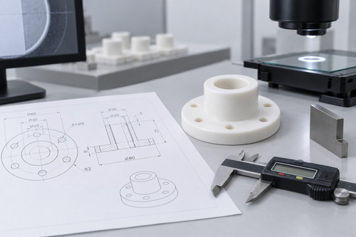
A useful ceramic drawing does more than define the outer shape. It tells the manufacturer which dimensions control function, which surfaces mate or seal, what loads and temperatures the part will see, and how compliance will be verified. That information matters because fired ceramics do not behave like ductile metals. They are hard, brittle, and sensitive to tensile stress and edge damage. A dimension that looks routine on a metal drawing may require diamond grinding, lapping, or a redesign when applied to an alumina custom part, zirconia component, silicon nitride part, or another technical ceramic.
The most reliable request for quotation separates functional requirements from preferences. Tight tolerances should be placed only where assembly, sealing, alignment, motion, or electrical performance requires them. Everything else should be left at a practical manufacturing tolerance. This reduces cost, shortens lead time, and gives the supplier room to choose the most stable process route.
Start With Function and Service Conditions
Before assigning dimensions, state what the component must do. Material selection and manufacturability depend on the complete operating environment, not on temperature or hardness alone. Two parts with the same geometry may need different ceramics if one carries tensile load, one sees rapid thermal cycling, and one contacts a molten metal or plasma.
- Maximum continuous temperature and short-duration peak temperature
- Heating and cooling rate, cycle frequency, and the location of the heat source
- Atmosphere, vacuum level, pressure, humidity, and chemical exposure
- Mechanical load direction, vibration, impact, and assembly preload
- Required electrical insulation, dielectric strength, thermal conductivity, or wear resistance
- Mating materials, joining method, sealing method, and coefficient-of-thermal-expansion constraints
- Expected service life and acceptable failure criteria
If the material has not been selected, provide these conditions instead of specifying only "ceramic." ACM's Ceramic Material Comparison Chart can be used for an initial comparison, but final selection should be based on grade-specific data, actual component geometry, and validated service conditions.
Define Geometry Without Creating Avoidable Stress
Technical ceramics generally undergo little plastic deformation and are sensitive to flaws, tensile stress, impact, and local stress concentrations. Where function allows, design the part so that loads are carried primarily in compression, use radiused or chamfered transitions instead of sharp corners or notches, and avoid abrupt thickness changes in components exposed to rapid temperature changes. These are functional design decisions because geometry, thermal gradients, and localized stresses can affect the reliability of brittle ceramic components.
|
Drawing feature |
Preferred approach |
Reason |
|
Internal corners |
Use a radius and identify the minimum acceptable radius |
Sharp internal corners concentrate tensile stress and are difficult to grind |
|
External edges |
Specify a chamfer or edge break where chipping would affect use |
Unprotected sharp edges are vulnerable during handling and assembly |
|
Holes near an edge |
Allow adequate ligament and identify whether the hole is critical |
A thin ligament raises local stress and breakage risk |
|
Wall thickness |
Keep sections uniform or use gradual transitions |
Abrupt changes create drying, firing, and thermal gradients |
|
Threads |
Discuss inserts, coarse ceramic threads, or an alternative joint |
Fine threads create fragile crests and expensive machining |
|
Press fits |
Avoid direct metal-style interference fits unless engineered |
Ceramics cannot yield to redistribute local assembly stress |
Use Datums and Functional Dimensions
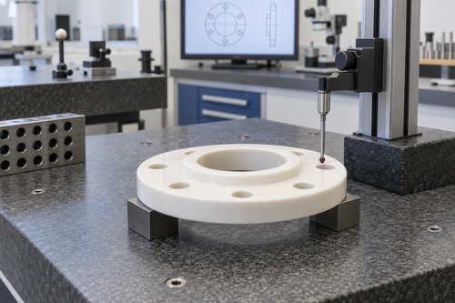
A supplier cannot infer the functional reference scheme from a dimension chain. Identify the primary mounting or sealing surface as a datum, then locate holes, bores, slots, and mating faces from that datum. This prevents tolerance accumulation and makes the inspection plan match the way the part is assembled.
- Choose a stable primary datum surface that represents how the part sits in the assembly.
- Choose a secondary datum that controls orientation without over-constraining the part.
- Dimension critical features from the datum system rather than from neighboring features.
- Mark dimensions as reference when they are informational and should not be inspected as acceptance requirements.
- State the drawing standard and units. Do not mix an informal sketch with an unexplained geometric-tolerancing frame.
Assign Tolerances by Manufacturing Stage
A ceramic feature may be formed before firing, machined in the softer green state, or finished after sintering. Fired dimensions reflect forming and sintering variation. Post-fired diamond grinding provides closer control but adds setup time, tool wear, and inspection. Lapping or polishing may be needed for flatness, parallelism, sealing, optical contact, or controlled roughness.
Do not apply one blanket tolerance to every dimension. A ±0.05 mm capability published for a particular alumina plate does not mean that every ceramic, size, thickness, hole pattern, and production quantity can hold the same value. Achievable tolerance depends on material, geometry, feature accessibility, aspect ratio, batch size, and whether the supplier can measure the feature reliably.
|
Requirement |
When it matters |
What to state |
|
Size tolerance |
Assembly clearance or feature location |
Nominal dimension, bilateral or unilateral tolerance, and datum |
|
Flatness |
Sealing, heat transfer, bonding, vacuum chucking |
Controlled surface, flatness tolerance, governing drawing standard, measurement method and sampling or scan strategy, support or fixturing condition, and whether the part is measured in a free or restrained state |
|
Parallelism |
Uniform gap, bearing, optical or electrode spacing |
Related datum face and allowable variation |
|
Perpendicularity |
Tube-to-flange or bore alignment |
Datum axis or datum plane |
|
Concentricity or runout |
Rotating parts and coaxial bores |
Rotation datum, measurement location, and total indicated runout if applicable |
|
Surface finish |
Seals, sliding contact, bonding, contamination control |
Ra or another defined parameter, cutoff/filter standard, and exact surface |
|
Edge condition |
Handling, dielectric field concentration, assembly |
Chamfer, radius, edge break, and whether chips are permitted |
Surface Finish Is Not the Same as Appearance
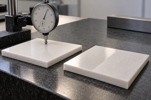
"Smooth," "polished," and "mirror finish" are not complete specifications. Surface roughness describes measured texture over a defined sampling condition. Flatness describes deviation of the entire surface from a plane. A surface can be smooth but not flat, or flat but too rough for a seal or thin-film process.
State the roughness parameter and unit, the surface to which it applies, and why it matters. If a sealing face requires lapping, identify the seal type and mating material. If a surface will be metallized, bonded, coated, or exposed to vacuum, state the downstream process so the supplier can control cleaning, edge handling, and residual surface damage.
Specify Inspection Before Production
A tolerance has little value if the buyer and supplier measure it differently. Define the measurement condition for critical features. Thin plates may change shape when clamped. Long tubes may sag under their own weight. Rough or translucent surfaces may require a different optical setup from a ground metal surface.
- Identify critical-to-function dimensions and the required inspection report.
- Specify whether flatness and runout are measured in a free state or fixture.
- State sampling requirements for production lots.
- List required material certificates, composition data, density, or mechanical-property reports.
- Define visual acceptance for chips, scratches, discoloration, pores, and edge damage with size limits or reference photographs.
- Agree on leak, dielectric, thermal, or proof testing only when it reflects the service requirement.
For first articles, ask the supplier to mark measured values on the same numbered drawing used for approval. This prevents a common problem in which a dimensional report is complete but cannot be traced to the buyer's feature numbering.
Provide a Quote Ready Package
|
Item |
Minimum information |
|
Drawing |
PDF for controlled review plus STEP, IGES, or another agreed 3D format for geometry |
|
Material |
Ceramic family and grade, or service conditions if selection support is needed |
|
Dimensions |
Units, datums, critical dimensions, realistic tolerances, and edge conditions |
|
Surface requirements |
Roughness, flatness, parallelism, polish, coating, metallization, and cleanliness |
|
Operating conditions |
Temperature profile, atmosphere, chemicals, load, vibration, voltage, and thermal cycling |
|
Quantity |
Prototype quantity, forecast production quantity, and lot schedule |
|
Quality documents |
Certificate of conformance, material certificate, dimensional report, test report, and sampling level |
|
Assembly information |
Mating materials, adhesive, braze, solder, clamp, seal, and required clearances |
ACM supplies machined alumina complex shapes, silicon nitride custom products, and other precision ceramic components. For an actionable review, attach the drawing to the inquiry form and identify the dimensions that control function. That is more useful than applying the tightest available tolerance to the entire part.
Final Review Before Sending the RFQ
- Does every tight tolerance have a functional reason?
- Can each critical feature be reached by the proposed machining and inspection equipment?
- Are internal corners, thin ligaments, and thickness transitions designed for a brittle material?
- Are roughness, flatness, and appearance specified separately?
- Are temperature changes and mating materials included, not only maximum temperature?
- Do the drawing, 3D model, purchase specification, and inspection requirements agree?
Resolving these questions before quotation usually saves more time than tightening the drawing after the first prototype. The goal is not the smallest possible tolerance. It is a specification that protects function and can be manufactured, inspected, and repeated.
References
1. Quinn, George D. *[NIST Recommended Practice Guide: Fractography of Ceramics and Glasses, 4th Edition](https://doi.org/10.6028/NIST.SP.960-16e4).* NIST Special Publication 960-16e4. National Institute of Standards and Technology, 2026.
5. International Organization for Standardization. *[ISO 1101:2017: Geometrical Product Specifications (GPS)—Geometrical Tolerancing—Tolerances of Form, Orientation, Location and Run-Out](https://www.iso.org/standard/66777.html).* ISO, 2017.
6. International Organization for Standardization. *[ISO 21920-2:2021: Geometrical Product Specifications (GPS)—Surface Texture: Profile—Part 2: Terms, Definitions and Surface Texture Parameters](https://www.iso.org/standard/72226.html).* ISO, 2021.
7. Advanced Ceramic Materials. "[Ceramic Material Comparison Chart](https://www.preciseceramic.com/ceramics-comparison-chart.html)." Accessed September 10, 2026.

{{item.content}}
LEVE A REPLY
{{item.children[0].content}}
{{item.content}}
LEAVE A REPLY
SUBSCRIBE OUR NEWSLETTER
- Why Do Kilns Need Both SiC Plates and SiC Tubes?
- Ceramic vs. Metallic Heating Elements: A Technical Selection Guide for Design Engineers
- Ceramic Heating Coil Versus Cotton Coil: Choosing the Better Fit
- 5 Ways Alumina Ceramic Plates Keep Heavy Industry Running
- Oxide, Sulfide, or Phosphate? A Supplier's Guide to Solid-State Electrolyte Ceramics
 1700°C Furnace Inquiry: Why Alumina Tube Isn't Enough & How to Specify Correctly
A clear and practical discussion on why selecting the proper alumina material is essential for continuous operation at 1700°C, along with a simple four-point checklist for proper specification.
READ MORE >
1700°C Furnace Inquiry: Why Alumina Tube Isn't Enough & How to Specify Correctly
A clear and practical discussion on why selecting the proper alumina material is essential for continuous operation at 1700°C, along with a simple four-point checklist for proper specification.
READ MORE >